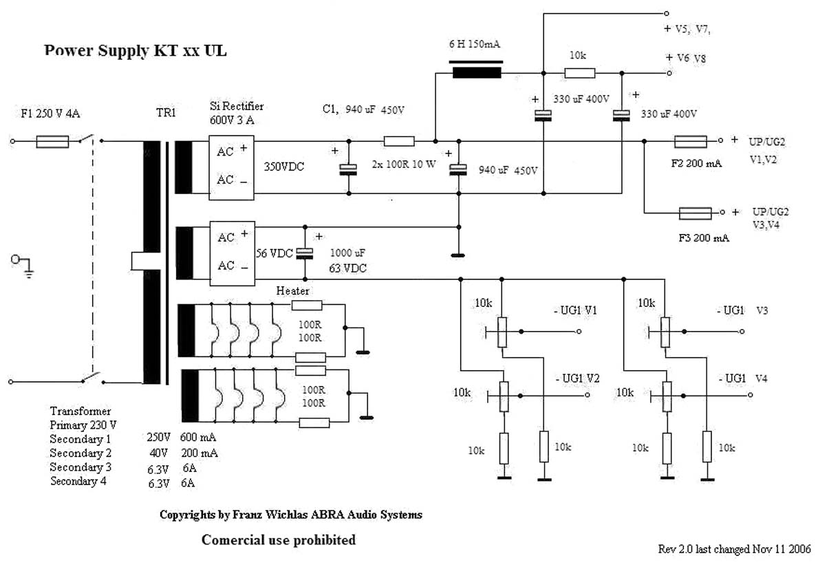
Vorab: Roehrengeraete werden im allgemeinen mit Spannungen betrieben,
die Lebensgefaehrlich sind. Bitte beachten Sie die einschlaegigen Schutzbestimmungen fuer den Umgang mit
Elektrizitaet !
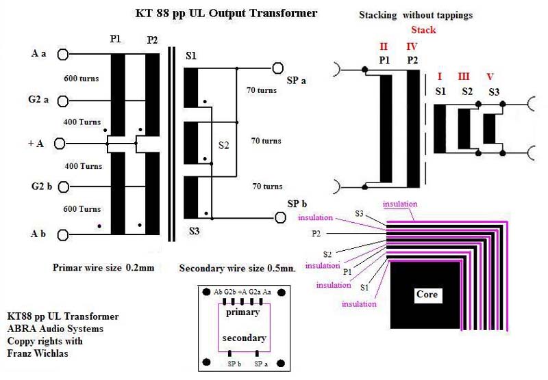
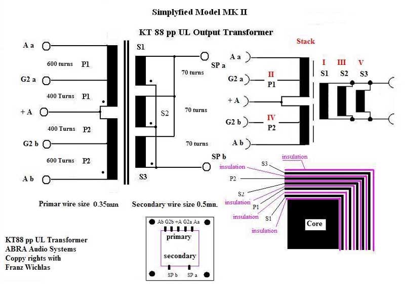

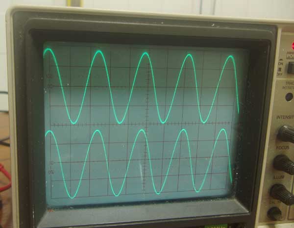
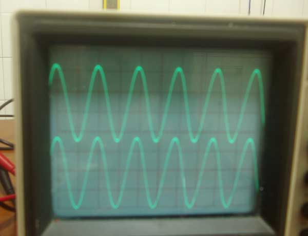
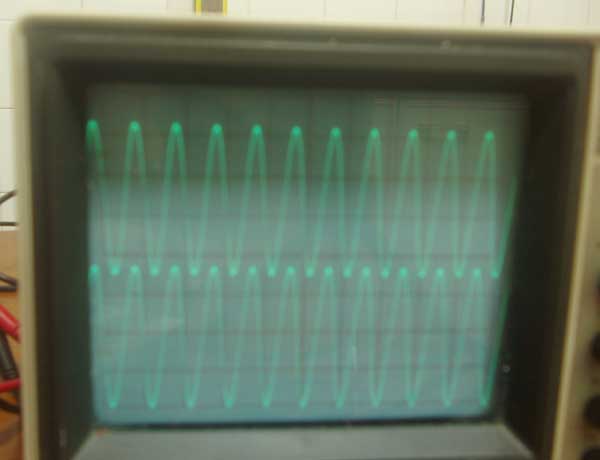
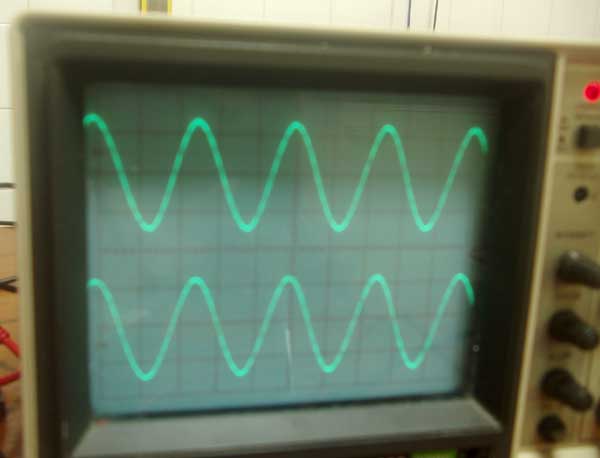
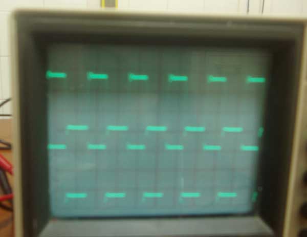


Frequenzgang des Ausgangs Uebertragers MK I
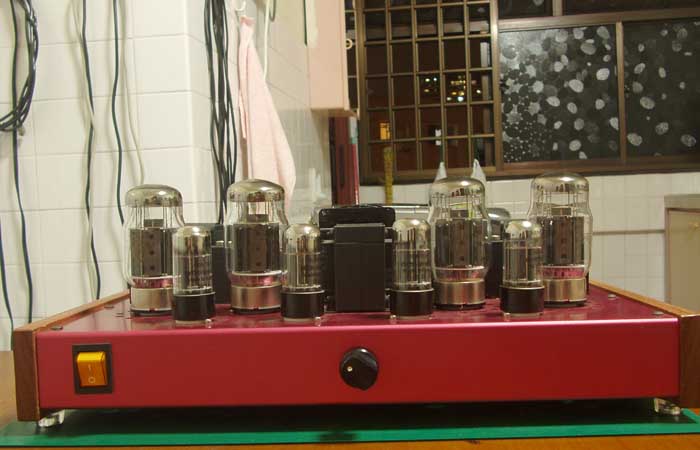
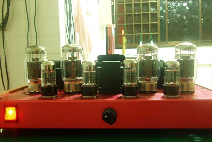
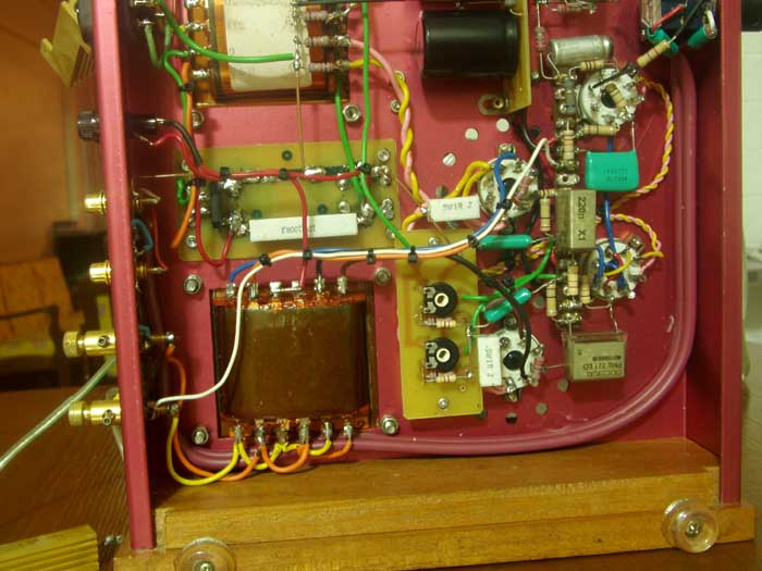
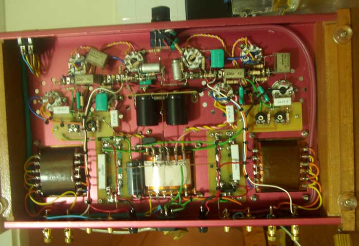
pp UL Verstaerker F&E ABRA MK I
Der Frequenzgang ist bei den im Artikel erwaehnten PA Roehren deckungsgleich.
KT88
|
Type |
Substitutes |
Base Diagram |
| KT88 |
 |
|
| Notes: | ||
GEC Type
KT88 BEAM TETRODE| Bulb | ST-16 |
| Base | Metal Shell Wafer Octal |
| Basing | 7S |
ELECTRICAL DATA
HEATER CHARACTERISTICS
| Heater Voltage |
6.3 |
Volts |
| Heater Current |
1.6 |
Amps |
DIRECT INTERELECTRODE CAPACITANCES
Triode Connection
| Grid No.1 to Plate, Grid No. 2 |
7.9 |
PF |
| Grid No. 1 to all but Plate and Grid No. 2 |
9.3 |
PF |
| Plate and Grid No. 2 to all but Grid No. 1 |
17.0 |
PF |
Tetrode Connection
| Grid No.1 to Plate |
1.2 |
PFf |
| Input |
16.0 |
PF |
| Output |
12.0 |
PF |
CHARACTERISTICS
| Plate Voltage |
250 |
Volts |
| Grid No. 2 Voltage |
250 |
Volts |
| Grid No. 1 Voltage (approx.) |
-15 |
Volts |
| Plate Current |
140 |
Ma |
| Grid No. 2 Current (approx.) |
3 |
Ma |
| Transconductance |
11500 |
?mhos |
| Plate Resistance |
12000 |
Ohms |
Triode Connected
| Plate and Grid No. 2 Voltage |
250 |
Volts |
| Plate and Grid No. 2 Current |
143 |
Ma |
| Grid No. 1 Voltage (approx.) |
-15 |
Volts |
| Transconductance |
12000 |
?mhos |
| Plate Supply Voltage |
560 |
Volts |
| Plate Voltage |
521 |
Volts |
| Grid No. 2 Voltage |
300 |
Volts |
| Plate Current per tube (Zero Signal) |
64 |
Ma |
| Plate Current per tube (Max Signal) |
73 |
Ma |
| Grid No. 2 Current per tube (Zero Signal) |
1.7 |
Ma |
| Grid No. 2 Current per tube (Max Signal) |
9.0 |
Ma |
| Load Resistance (Plate to Plate) |
9000 |
Ohms |
| Cathode Bias Resistor1 |
460 |
Ohms |
| Grid No. 1 Voltage |
-30 |
Volts |
| Power Output |
50 |
Watts |
| Total Harmonic Distortion |
3 |
Percent |
| Intermodulation Distortion2 |
11 |
Percent |
| Anode Dissipation (Zero Signal) |
33 |
Watts |
| Anode Dissipation (Max Signal) |
12 |
Watts |
| Grid No. 2 Dissipation (Zero Signal) |
0.5 |
Watts |
| Grid No. 2 Dissipation (Max Signal) |
2.7 |
Watts |
| Plate Supply Voltage |
560 |
Volts |
| Plate Voltage |
552 |
Volts |
| Grid No. 2 Voltage |
300 |
Volts |
| Plate Current per tube (Zero Signal) |
60 |
Ma |
| Plate Current per tube (Max Signal) |
145 |
Ma |
| Grid No. 2 Current per tube (Zero Signal) |
1.7 |
Ma |
| Grid No. 2 Current per tube (Max Signal) |
15.0 |
Ma |
| Load Resistance (Plate to Plate) |
4500 |
Ohms |
| Grid No. 1 Voltage1 |
-34 |
Volts |
| Power Output |
100 |
Watts |
| Total Harmonic Distortion |
2.5 |
Percent |
| Intermodulation Distortion2 |
10 |
Percent |
| Anode Dissipation (Zero Signal) |
33 |
Watts |
| Anode Dissipation (Max Signal) |
28 |
Watts |
| Grid No. 2 Dissipation (Zero Signal) |
0.5 |
Watts |
| Grid No. 2 Dissipation (Max Signal) |
4.5 |
Watts |
AB1 Push-Pull, Cathode Bias,
Ultra-Linear Connection (40% tap)
| Plate and Grid No. 2 Supply Voltage |
500 |
375 |
Volts |
| Plate and Grid No. 2 Voltage |
436 |
238 |
Volts |
| Plate and Grid No. 2 Current per tube (Zero Signal) |
87 |
87 |
Ma |
| Plate and Grid No. 2 Current per tube (Max Signal) |
99 |
96 |
Ma |
| Load Resistance (Plate to Plate) |
6000 |
5000 |
Ohms |
| Cathode Resistor1 |
600 |
400 |
Ohms |
| Grid No. 1 Voltage |
-52 |
-35 |
Volts |
| Power Output |
50 |
30 |
Watts |
| Total Harmonic Distortion |
1.5 |
1.0 |
Percent |
| Intermodulation Distortion2 |
4 |
3 |
Percent |
| Anode and Grid No. 2 Dissipation (Zero Signal) |
38 |
28.5 |
Watts |
| Anode and Grid No. 2 Dissipation (Max Signal) |
17 |
16 |
Watts |
| Output Impedance |
4800 |
4500 |
Ohms |
AB1 Push-Pull, Fixed Bias, Ultra-Linear
Connection (40% tap)
| Plate and Grid No. 2 Supply Voltage |
560 |
460 |
Volts |
| Plate and Grid No. 2 Voltage |
553 |
453 |
Volts |
| Plate and Grid No. 2 Current per tube (Zero Signal) |
50 |
50 |
Ma |
| Plate and Grid No. 2 Current per tube (Max Signal) |
157 |
140 |
Ma |
| Load Resistance (Plate to Plate) |
4500 |
4000 |
Ohms |
| Grid No. 1 Voltage3 |
-75 |
-59 |
Volts |
| Power Output |
100 |
70 |
Watts |
| Total Harmonic Distortion |
2 |
2 |
Percent |
| Intermodulation Distortion2 |
11 |
10 |
Percent |
| Anode and Grid No. 2 Dissipation (Zero Signal) |
27.5 |
22.5 |
Watts |
| Anode and Grid No. 2 Dissipation (Max Signal) |
33 |
27 |
Watts |
| Output Impedance |
7000 |
6500 |
Ohms |
AB1 Push-Pull, Cathode Bias, Triode
Connection
| Plate and Grid No. 2 Supply Voltage |
400 |
485 |
Volts |
| Plate and Grid No. 2 Voltage |
349 |
422 |
Volts |
| Plate and Grid No. 2 Current per tube (Zero Signal) |
76 |
94 |
Ma |
| Plate and Grid No. 2 Current per tube (Max Signal) |
80 |
101 |
Ma |
| Load Resistance (Plate to Plate) |
4000 |
4000 |
Ohms |
| Grid No. 1 Voltage |
-40 |
-50 |
Volts |
| Power Output |
17 |
31 |
Watts |
| Total Harmonic Distortion |
1.5 |
1.5 |
Percent |
| Intermodulation Distortion2 |
5.6 |
5.6 |
Percent |
| Anode and Grid No. 2 Dissipation (Zero Signal) |
26.5 |
40 |
Watts |
| Anode and Grid No. 2 Dissipation (Max Signal) |
19 |
27 |
Watts |
| Cathode Resistor |
525 |
525 |
Ohms |
| Output Impedance |
2000 |
1900 |
Ohms |
NOTES:
INSTALLATION
Mein KT66-Amp folgt bald nach,
viel Spass beim Hobby,
Franz und Elisabeth aus Singapore